Showing posts with label mesh. Show all posts

2024/07/24

Look, a finished project!

Hi! Lussy here.
Realizing that we haven't posted yet this year was kind of a shock.

Many things happened this year. I had an ankle surgery during winter, which slowed things down considerably, and we went through several family emergencies. Rough year so far.


But on the bright side, I finally finished a personal project! I 3D modeled Hyde's (of L'Arc~en~Ciel, VAMPS and The Last Rockstars fame, and he's also active solo!) custom guitar.

(no, it's not a typo. hyde writes his name lowercase for L'Arc, and uppercase for his other bands and his solo project.)

The model and textures were made by me, with Geril assisting with fixing various issues and figuring out the normal baking process, and then he did most of the setup inside Sketchfab.

I started the project pretty much as soon as this article was released about the guitar. The end of 2022 was a nightmare however, and things went downhill for a long time, and I can't even say we're fully back on track right now. But we did have enough energy to complete this, so that's something!

The model itself was done pretty quickly. There was a lot of photo hunting, and watching live performances frame by frame to see if the image was sharp enough to reference, and figuring out what custom parts were used for the guitar. I went as far as to look up the details of the stock Les Paul Junior model and use the exact fretboard radius. I went hard. I have a full gallery of totally non-psychotic guitar closeups now.

What took the longest was the art plate. I couldn't find a photo big enough to get a 4K texture off it, and some parts were always obscured, so I had to improvise for some of it. In the end I redrew the whole thing, even the parts I could sample off of photos, because the resolution varied so much and I couldn't bear having inconsistencies. So I sat with my tablet for hours at a time, over the course of months, and it slowly came together.

I'm happy with how it came out, and it was nice to work on something not for profit or recognition or whatever (although I did post it online, so this is a bit hypocritical), but just because I could. It's not like I'm going to use this model for anything, it's not playable, it doesn't physically exist now, it just looks pretty. And I think I really needed that after working in 3D and games for so long.

I am considering other projects like this one - I considered modeling Hyde's microphone as well, because it has a crazy art plate similar to this one, and apparently I like torturing myself with that, but time will tell if that is going to happen, I guess.

And now to figure out what to do with all this unreasonably in-depth guitar knowledge I gained.

2019/03/31

Continuing a past project!

This month, we went back to one of our older projects that we were stuck on. It was this one, originally intended to be a character that utilizes mesh swapping for expressions. We decided to go ahead and make her into a more regular character so we can use her on any platform. She still has a video game associated with her, but it's only at the concept phase and so we're just concentrating on the character for now.


We plan to publish a scene with her on Sketchfab, because it's been *checks Sketchfab* almost two years since we've published anything (but we're still getting new followers).
We probably won't let it be an actual 2 years of hiatus.

For now, it's still a work in progress of course, but we'll share some images anyways.


We decided to continue this character because we've been having a rough time with work and we're a little burnt out. I (Lussy) am tired of working with Blueprints all the time, and it's been about a year since I properly textured anything, and Geril's happy to be working with only a few bones and a basic rig. So I got to texturing and Geril made the mesh, rig and animations as usual.

For now, we only concentrated on the face and mimicry, so the body is a work in progress in every aspect.

In other news, we finished a prototype of the Oregon Trail project in the first week of the month. Because we worked with a history teacher, we took his advice and made the game more quiz-like. Now the baked project is in full Hungarian, and we haven't really made any new assets for it, just used some from the previous historical projects.
It's not that impressive or anything – it was done quite quickly – but it has a lot of modules and possibilities.
Here's a video.

2016/07/31

Tutorial: Dynamically changing facial normal maps in Unreal Engine 4

Hi!

We've promised more tutorials, and we've specifically promised a tutorial on dynamic facial normal maps in UE4. So here it is! Before we begin...

It took a long time to get started with these, because we were busy with other works, our own projects, and with learning a LOT about the engine. So for now, we didn't really progress with the actual project of Lemniscate, but this recently acquired knowledge will speed us up when we do have time to progress.

Now, on to the tutorial.

***

To start out, you must have a finished face model with bone-driven morph targets. You'll have to decide which morphs should activate normal map changes. For example, Sal here has normal maps for raising each individual eyebrow, for frowning, for raising the inner portion of his eyebrows, and for opening his mouth. For a human, there could be additional wrinkles on the nose, under the eyes and such. Because Sal has fur, these normal maps are pretty subtle.
We will probably use a different technology for him, since we use NeoFur now for the fur effect, so this is only for demonstration.
We are using Blender and GIMP in this tutorial, but you can use any modeling and photo editing software you like. But Blender and GIMP are free, so no excuses!


First, you'll have to remove every part of the skeletal mesh that is irrelevant. The only parts to stay should be the parts with the material that will make use of the dynamic normal map (so, in this case, the face).


Duplicate the head. Make one for every morph target you want to influence the normals, and then apply the chosen morphs to the heads, one morph to one mesh.


Duplicate all of the heads again, make a new version that removes absolutely everything other than the parts where you want the normals to change (so the neck, back of the head, ears have to go). Then apply a multires modifier and set it to about x4, so that you can make details on the face with the sculpt tool.


Don't worry about anything else other than the wrinkles, because this normal map will be added to the default normal, so all the base normal map details will still be visible. It's better if you don't make overlapping wrinkles, because all of these will be combined into a single normal map later.


After you're done with sculpting, bake normal maps from each of the sculpted faces onto the original meshes (you can find our tutorial on normal map baking with Blender here, the only thing different here is using multires). Optionally you can also bake ambient occlusion maps for more illusion of depth, which we didn't, but you can operate them the same way as the normals.


After you're done baking all of them, combine them into a single file (this is the part where you can make adjustments if you have overlapping wrinkles!)


Next, you'll have to make masks for using this additional normal map. It's best if you use the image file's channels for separating different masks. Because a mask only uses greyscale values, you can combine up to 4 of them into a single image file using the red, green, blue and alpha channels. The ideal format to use for this is the Targa format (.tga), because it keeps the channels clean and separate. You can use GIMP or Photoshop to edit the channels individually, but you can probably use any other photo-manipulation software for this as well.


I've created six different wrinkles, so I will save them as two .tga files using the r, g, b channels. Use a black background. When editing the channels, you'll have to use white to fill the spaces where the individual wrinkled spots are.


These will indicate the areas where you want to add your new wrinkle normal map to the default one. After finishing, combine the channels into colored .tga files and save.


It's time to open up Unreal 4. 


Import the new normal map and the masks, and put them inside the character's material. Arrange the mask textures below each other and add a multiply node next to each of their channels. Connect scalar parameters to the other input of the multiply nodes and name them appropriately - for example, the parameter next to the mask controlling the wrinkles above the left eyebrow will be called BrowUp_L. Name all of them, and make sure not to change their default values from 0.

Create  LinearInterpolation nodes (Lerp nodes) for all of the masks, and chain them together using their A inputs. Create a three value texture sample node (hold down 3 and click with the left mouse button) and set the third value (blue) to 1 (so, 0,0,1) or just use an empty normal map. Connect this into the first Lerp node's A input.

Connect the multiply nodes to the Lerp nodes' alpha inputs, and our new normal map into the Lerp nodes' B inputs. The last Lerp node's output should go into a BlendAngleCorrectedNormals node's AdditionalNormal input, and the original normal map should be connected to the BaseNormal input. Connect the last output to the final material input node's Normal input.

You are done with the material editor, let's get started with preparing the skeleton!


These are bone driven morph targets. Currently there isn't a node for getting the value of a morph target in Blueprints (the 'get morph target' node doesn't return any other value other than 0, correct me if I'm wrong about this). So what we have to do is create sockets for each bone that drives a morph target that we want to add dynamic normal maps to. Then you should rotate the morph targets to such a position that you can easily remember and calculate with - you should choose a rotation axis (in my case, X) that matches with the rotation of the bone that drives the morph.
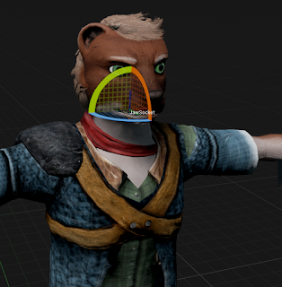

So, in an ideal case, when the morph target's value is 1, the bone's local X rotation is 90 degrees, and the socket's should read the same. When the value is -1, the rotation should read -90 degrees. This is important, because if the degrees are, for example, 90 for neutral, 0 for -1 and 180 for 1, then the 180 degrees will cause problems. In Unreal, if the degree would go above 180, it becomes -180, which is a nightmare when working with clamps. So, ideally just stick to -90, 0 and 90 degrees.

You can see the socket's local rotations in the Skeleton view if you select them while an animation is playing. You can also output them in a print node and check while playing, or right click on them in a blueprint, 'watch' them and the values will appear on the blueprint while the game is playing.

Let's move on to the animation blueprint that drives all of this!


It's pretty big, so you may have to download it to see it properly

You may get all of it by just looking at the picture, but I'll explain everything below.

You need to add this to the character's anim blueprint's event graph's Update Animation event. I've added a bool that can turn off the whole thing if it's not needed. Then, the blueprint makes sure that the variable holding the material of the face isn't empty; if it is, the blueprint will create a dynamic material out of the appropriate material and use that. (The dynamic part is important, parameters can only be updated in dynamic materials, and so far I've only managed to create them during runtime. So this part will happen when the anim blueprint starts updating.)

Then comes the math. I'll show you the easiest example: you want to figure out when to activate the normal map for wrinkling the forehead above the left brow. You'll have to get the appropriate morph target's socket's rotation first (make sure that you get the rotation in component space - the rotation compared to the original rotations of the socket, not in world space, because that rotation is compared to the world's rotation. You can get component space by using the Socket Transform node instead of the simple rotation node). In our case, when the morph target's value is 1, the socket's rotation is 90.

The material parameter's values are: 0 for invisible, 1 for completely visible, everything in between is partly visible, visibility depending on the number. For this reason, we have to assign 90 degrees to the number 1, and 0 degrees to the number 0. The easiest way to do this is using the 'normalize to range' node. This node lets you type in a minimum and maximum value, and outputs the position of the input number on this scale as a number from 0 to 1 (for example, on a range of 0 to 100, 87 would be 0,87).

After we got this number, we just have to set it as the scalar material parameter controlling the normal map's opacity, and we're done. It's a good idea to clamp the values of the socket rotations, because animations - obviously - are not clamped to a 90 degrees of movement, there can be slip-ups. (This is where the jump from 180 to -180 would make things hard: -180 is well below 0 or even -90, so it would instantly make the value go from 1 to 0, thus make the normalmap invisible, which is something that we don't want.)

A slightly more complicated version is if both the positive and negative morph target values are bound to normal maps. You'll have to do the first part the same way, but you have to get the absolute value of the rotation degrees of the socket (negative numbers become positive, positive numbers stay positive), and then normalize to range. The rest is the same.

The only other variation we're using is multiple morph targets triggering the same normal map. If you want some of the morphs to affect the normal map's opacity a little less then others, you'll have to multiply the output amount by some less-than-1 number, like 0.8. At the end, you'll have to add all the affecting morph's values together, then clamp the resulting number between 0 and 1. That's all there is to it, really.

For testing, I suggest you create a morph target test animation where you operate all of the morphs individually and in order. You'll be able to clearly see if all of the morphs are working. For me, there was a lot of trial and error involved, but you could minimize this by clearly noting and setting all the socket's rotations.

Subtle wrinkles on the forehead
Less subtle nasolabial folds
If you have any questions or suggestions, leave a comment below!

2013/11/05

Tutorial: Making "cheap" grass, from Blender to UDK

Hi, I'm Geril, and in this tutorial I'm going to show you how to make a static environment object in a step by step tutorial using Blender and the UDK. In this case the object is a patch of grass.

First, we need a mask. A mask is a black and white image on which white means visible, and black means invisible. The image should have no grey, only black and white. The one I'm using is 512*512 pixels. (Unreal 3 only recognizes binary numbers for resolution. So: 64*64, 128*128, 256*256, 512*512, 1024*1024, 2048*2048)
Other than the mask, you also need a diffuse texture that shows on the surface of the grass. Right now I'm using one that isn't an actual grass texture, but of course it's better to create your own or select one from the UDK's files.

Open up Blender (v2.63 is what I'm using). In the 3d view the first thing you see is a cube that Blender loads on startup. We don't need this cube so you can delete it. The basic controls are: middle mouse button for rotating the view, and shift + middle mouse button for moving the camera.

Load your texture in the UV/Image editor section. In the 3D view, add a simple plane: ADD/MESH/PLANE. From this point on, we're going to edit the plane in edit mode. 
Press Tab to enter edit mode.

Let's rotate the plane 90 degrees on the X axis.


To do this precisely, press R, X and then type 90, otherwise just use the 3D rotate manipulator.

After this is done, we'll unwrap the UV of the plane on the texture. Just select all the vertices (with shift you can multi-select), the press U and then Unwrap. Since the plane is really simple, its UV won't be too complicated.


The plane needs to be a little lower on the Z axis, so let's move it. Select all vertices, then press G to grab it. If you press Z after G, the plane will only move on the Z axis. Also, holding down CTRL whilst moving the plane will make it move according to the grid, and shift will slow the movement down. Make it so that the plane is a little under the X and Y axes, so it won't float over the ground.


Unless the player has no chance to go near it or look at it from different angles, a single plane doesn't make our grass believable at all, so let's duplicate this plane.
Select it and press Shift + D, then rotate it 90 degrees on the Z axis. You can repeat this step if you want a more detailed patch of grass, and you can even use different masks for each plane.


Now you should subdivide your object, so that it doesn't stay flat and you can change its shape a bit.
Select all, press W and subdivide. After this, you can make adjustments to the UV by moving its vertices (G key).
It's important to note that while Blender uses one-sided faces by default, in the Unreal Engine 3 it's easy to set it to two-sided faces.
You need to add at least one material to the object. You need more if you used more than one masks. In that case, you have to assign a different material to every plane that has a different mask.

The current size of the grass would be tiny in the UDK, so let's make it about 20 times as big. Select all and press S, then type 20. Afterwards you want to adjust the placing because it most likely isn't in the right place.

Now we need to name the object. In 3D view, on the right sidebar, open Item and type in the name (replacing the default name "Plane").
 The only thing left to do in Blender is exporting. Exit edit mode (Tab), then select File>Export, and Autodesk FBX. In the left sidebar, check the "Selected Objects" box, and make sure that only the "Mesh" button is selected underneath. Name the file and export it to the desired location. 

Start the UDK. After closing the Welcome window, look at the Content Browser. In the lower left corner of it, click import. Find your exported FBX file, the mask(s), and the diffuse texture (if you made one), and open them.


If you already have a package, use that, if you don't, create one now and import your files. Grouping is also useful. The UDK is able to import the used textures from the FBX file, but I recommend you import them seperately, because depending on your version, it can cause errors.
The UDK may warn you that the FBX version is outdated, but this doesn't matter with static meshes. After the importing, find your files in the Content Browser, right click on the mask texture, and click "Create New Material". Name it, and after creating, open it.

In the Material Editor, you can see your mask in a box, and you can move the box around by holding CTRL and dragging it. Let's put it beside the Opacity Mask node, and connect the mask's black colored node to the Opacity Mask's node. In the properties section under Material, set Blend Mode from Opaque to Masked, then the Lighting Model to NonDirectional, then check the box below that says "Two Side". We only need a diffuse texture now. Put your own, or your selected one over the mask, and connect its black colored node into the Diffuse node. Save (the green check on the upper left) and close the window.

Let's open our static mesh, in the right sidebar open LODInfo, and look for 0. Elements 0. Material. Switch to the content browser and select the material we just made. Back in the StaticMesh Editor, click the green arrow next to the Material to assign it to the mesh.
If you've done all these steps correctly, the mesh is now complete and usable, you can rotate it with the right mouse button and zoom in and out with the left mouse button.


As the last step, let's drag and drop the static mesh from the Content Browser into the level. Pressing the space bar, you can manipulate the mesh. In the level you can move with WASD and the left and right mouse button.

Of course this is a really basic object. The grass used in our game, for example, is also influenced by the wind. This works based on the material. In the Unreal Engine 3 there are tons of possibilities, and in later posts I'd like to share some of the ones I discovered and learned.

I'm happy to answer any questions in the comment section. I'm also open for any requests you might have.

Have a nice day!