Showing posts with label blender. Show all posts

2024/07/24

Look, a finished project!

Hi! Lussy here.
Realizing that we haven't posted yet this year was kind of a shock.

Many things happened this year. I had an ankle surgery during winter, which slowed things down considerably, and we went through several family emergencies. Rough year so far.


But on the bright side, I finally finished a personal project! I 3D modeled Hyde's (of L'Arc~en~Ciel, VAMPS and The Last Rockstars fame, and he's also active solo!) custom guitar.

(no, it's not a typo. hyde writes his name lowercase for L'Arc, and uppercase for his other bands and his solo project.)

The model and textures were made by me, with Geril assisting with fixing various issues and figuring out the normal baking process, and then he did most of the setup inside Sketchfab.

I started the project pretty much as soon as this article was released about the guitar. The end of 2022 was a nightmare however, and things went downhill for a long time, and I can't even say we're fully back on track right now. But we did have enough energy to complete this, so that's something!

The model itself was done pretty quickly. There was a lot of photo hunting, and watching live performances frame by frame to see if the image was sharp enough to reference, and figuring out what custom parts were used for the guitar. I went as far as to look up the details of the stock Les Paul Junior model and use the exact fretboard radius. I went hard. I have a full gallery of totally non-psychotic guitar closeups now.

What took the longest was the art plate. I couldn't find a photo big enough to get a 4K texture off it, and some parts were always obscured, so I had to improvise for some of it. In the end I redrew the whole thing, even the parts I could sample off of photos, because the resolution varied so much and I couldn't bear having inconsistencies. So I sat with my tablet for hours at a time, over the course of months, and it slowly came together.

I'm happy with how it came out, and it was nice to work on something not for profit or recognition or whatever (although I did post it online, so this is a bit hypocritical), but just because I could. It's not like I'm going to use this model for anything, it's not playable, it doesn't physically exist now, it just looks pretty. And I think I really needed that after working in 3D and games for so long.

I am considering other projects like this one - I considered modeling Hyde's microphone as well, because it has a crazy art plate similar to this one, and apparently I like torturing myself with that, but time will tell if that is going to happen, I guess.

And now to figure out what to do with all this unreasonably in-depth guitar knowledge I gained.

2018/02/28

Character face rig!

Hi!

Geril here. This month in my free time, just to expand our portfolio a little, I've created a new character. It's still heavily work-in-progress, but it's gotten interesting enough to show you! It's a standard character for use in Unreal 4 and made in Blender, as usual, but this time instead of creating our own skeleton from scratch, I made the skeleton based on this .blend file recommended by Epic for Unreal 4.


While I kept the bone structure and names of the original skeleton, I modified everything I needed to to suit the character, and - as always - I made a specific and unique facial rig. If you've been our reader for a while, you might have noticed that we prefer using shape keys/morph targets for our characters' faces. It's true that they are easier to use for games, but they also limit things quite a bit. And even though I love limitations, because limitations force me to be creative, it was about time for me to step out of my comfort zone and create a dedicated video game character complete with a bone-driven face rig. So I did. The face has a lot of bones that are constrained to a bunch of driver bones for easier use, so within a few seconds I can animate stupid faces for the poor character.


At least that's how it started.


Right now on the pictures and the attached video is a face with standard driver bones. The eyes will move by texture panning, but what will really be interesting is that we plan to swap out parts of the skeletal mesh during runtime. At first this might sound strange, especially for a rig like this, but we want to see how well the Unreal Engine handles this stuff.

The mesh swaps will happen on the fly: the face will be split into multiple smaller meshes (the splits will be invisible of course), and for example when the character blinks, the eye meshes will switch to a closed-eyed mesh version instead of the eyelids stretching over the eyes. We will need multiple meshes which are spread out in-between the open and closed eye states to make a smooth animation, and then we still have to solve how to handle the textures for these meshes. The upside is that we don't have to worry about texture stretching, because we'll be using separate meshes for O and U sounds, and even for sticking the tongue out.


But first we'll need a finished and stable face rig that could work standalone as well. The separate mesh pieces will be created using these weights too, and then modified in a way that leaves most of the weights intact. That way if the lips have a smile on them, and the mesh changes to an O-sound, the smile will stay. It sounds weird in text, but if all goes according to our plans, it should work pretty well. We'll have to change our animation style a bit to fit this technology, maybe make it snappier so the mesh changes won't look abrupt. The only question remaining is how UE4 will react to this all.

While I'm still working on the rig, Lussy's making the textures for the character. This takes up most of our free time now, so look forward to more posts about it in the coming months!

2016/11/28

3D Yuumei Fanart: Frey Underground!

Hey!

We've had some free time this month, and decided to mix things up a bit. This is completely unrelated to any of our previous stuff - it's a fanart of Yuumei's Underground picture.

The whole thing started when we realized that our portfolio was a little... one-sided. Not everyone likes the OLP stuff and style, but until now, that was the only thing we could showcase as a team. Separately we've worked in many different styles, but together we've mostly worked in one. So we've decided to try out different styles and subjects for practice, experimentation, and for our portfolio. This was also a challenge for us, to see how far we can get in about a week and how efficient we are. We've probably went a little overboard, but oh well.

Frey, the character is fully rigged and has a morph target set for emotions and complete lip-syncing. Basically we've created a game-ready character as fast as we could.

We've planned to include a violin playing and a random goofy animation as well, but exporting into Sketchfab-friendly FBX made our work hard. The process was very tedious and took up almost a whole additional day. (We're now convinced that Blender hates us) We can't include those animations in the same scene we've uploaded, and we thought making a new scene just for that would be overkill. Maybe we'll upload it someday, if people are interested.

We've decided on this particular piece because I [Lussy] am a long time fan of Yuumei and thought that shiny PBR lights would go well with her art style. It was refreshing to work based on someone else's "concept art". Can't wait for Fisheye Placebo to continue!

Here are some WIP pics:

Frey isn't happy with his incomplete hair
Attack of the placeholder normalmaps
Frey's violin in Sketchfab's editor
Some of Frey's test expressions and lip-sync
We love Sketchfab, and it's a shame that it isn't more popular. Whenever we show Sketchfab links or embeds to someone, we have to explain that it isn't a picture or a video, and that the camera can be moved. We always have to either explain the exact controls and settings (for example, this model always loads in SD quality and you have to manually set it to HD) in a wall of text, or leave out the instructions and hope very strongly that people will try clicking on the model. We went with the latter this time.

We hope you liked it! We were trying hard not to butcher the scene. Hope we didn't.

2016/07/31

Tutorial: Dynamically changing facial normal maps in Unreal Engine 4

Hi!

We've promised more tutorials, and we've specifically promised a tutorial on dynamic facial normal maps in UE4. So here it is! Before we begin...

It took a long time to get started with these, because we were busy with other works, our own projects, and with learning a LOT about the engine. So for now, we didn't really progress with the actual project of Lemniscate, but this recently acquired knowledge will speed us up when we do have time to progress.

Now, on to the tutorial.

***

To start out, you must have a finished face model with bone-driven morph targets. You'll have to decide which morphs should activate normal map changes. For example, Sal here has normal maps for raising each individual eyebrow, for frowning, for raising the inner portion of his eyebrows, and for opening his mouth. For a human, there could be additional wrinkles on the nose, under the eyes and such. Because Sal has fur, these normal maps are pretty subtle.
We will probably use a different technology for him, since we use NeoFur now for the fur effect, so this is only for demonstration.
We are using Blender and GIMP in this tutorial, but you can use any modeling and photo editing software you like. But Blender and GIMP are free, so no excuses!


First, you'll have to remove every part of the skeletal mesh that is irrelevant. The only parts to stay should be the parts with the material that will make use of the dynamic normal map (so, in this case, the face).


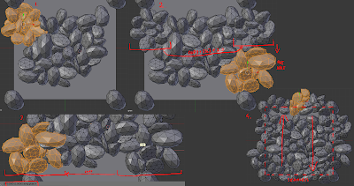
Duplicate the head. Make one for every morph target you want to influence the normals, and then apply the chosen morphs to the heads, one morph to one mesh.


Duplicate all of the heads again, make a new version that removes absolutely everything other than the parts where you want the normals to change (so the neck, back of the head, ears have to go). Then apply a multires modifier and set it to about x4, so that you can make details on the face with the sculpt tool.


Don't worry about anything else other than the wrinkles, because this normal map will be added to the default normal, so all the base normal map details will still be visible. It's better if you don't make overlapping wrinkles, because all of these will be combined into a single normal map later.


After you're done with sculpting, bake normal maps from each of the sculpted faces onto the original meshes (you can find our tutorial on normal map baking with Blender here, the only thing different here is using multires). Optionally you can also bake ambient occlusion maps for more illusion of depth, which we didn't, but you can operate them the same way as the normals.


After you're done baking all of them, combine them into a single file (this is the part where you can make adjustments if you have overlapping wrinkles!)


Next, you'll have to make masks for using this additional normal map. It's best if you use the image file's channels for separating different masks. Because a mask only uses greyscale values, you can combine up to 4 of them into a single image file using the red, green, blue and alpha channels. The ideal format to use for this is the Targa format (.tga), because it keeps the channels clean and separate. You can use GIMP or Photoshop to edit the channels individually, but you can probably use any other photo-manipulation software for this as well.


I've created six different wrinkles, so I will save them as two .tga files using the r, g, b channels. Use a black background. When editing the channels, you'll have to use white to fill the spaces where the individual wrinkled spots are.


These will indicate the areas where you want to add your new wrinkle normal map to the default one. After finishing, combine the channels into colored .tga files and save.


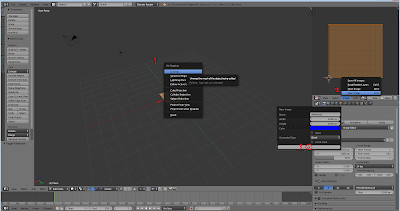
It's time to open up Unreal 4. 


Import the new normal map and the masks, and put them inside the character's material. Arrange the mask textures below each other and add a multiply node next to each of their channels. Connect scalar parameters to the other input of the multiply nodes and name them appropriately - for example, the parameter next to the mask controlling the wrinkles above the left eyebrow will be called BrowUp_L. Name all of them, and make sure not to change their default values from 0.

Create  LinearInterpolation nodes (Lerp nodes) for all of the masks, and chain them together using their A inputs. Create a three value texture sample node (hold down 3 and click with the left mouse button) and set the third value (blue) to 1 (so, 0,0,1) or just use an empty normal map. Connect this into the first Lerp node's A input.

Connect the multiply nodes to the Lerp nodes' alpha inputs, and our new normal map into the Lerp nodes' B inputs. The last Lerp node's output should go into a BlendAngleCorrectedNormals node's AdditionalNormal input, and the original normal map should be connected to the BaseNormal input. Connect the last output to the final material input node's Normal input.

You are done with the material editor, let's get started with preparing the skeleton!


These are bone driven morph targets. Currently there isn't a node for getting the value of a morph target in Blueprints (the 'get morph target' node doesn't return any other value other than 0, correct me if I'm wrong about this). So what we have to do is create sockets for each bone that drives a morph target that we want to add dynamic normal maps to. Then you should rotate the morph targets to such a position that you can easily remember and calculate with - you should choose a rotation axis (in my case, X) that matches with the rotation of the bone that drives the morph.


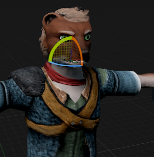
So, in an ideal case, when the morph target's value is 1, the bone's local X rotation is 90 degrees, and the socket's should read the same. When the value is -1, the rotation should read -90 degrees. This is important, because if the degrees are, for example, 90 for neutral, 0 for -1 and 180 for 1, then the 180 degrees will cause problems. In Unreal, if the degree would go above 180, it becomes -180, which is a nightmare when working with clamps. So, ideally just stick to -90, 0 and 90 degrees.

You can see the socket's local rotations in the Skeleton view if you select them while an animation is playing. You can also output them in a print node and check while playing, or right click on them in a blueprint, 'watch' them and the values will appear on the blueprint while the game is playing.

Let's move on to the animation blueprint that drives all of this!


It's pretty big, so you may have to download it to see it properly

You may get all of it by just looking at the picture, but I'll explain everything below.

You need to add this to the character's anim blueprint's event graph's Update Animation event. I've added a bool that can turn off the whole thing if it's not needed. Then, the blueprint makes sure that the variable holding the material of the face isn't empty; if it is, the blueprint will create a dynamic material out of the appropriate material and use that. (The dynamic part is important, parameters can only be updated in dynamic materials, and so far I've only managed to create them during runtime. So this part will happen when the anim blueprint starts updating.)

Then comes the math. I'll show you the easiest example: you want to figure out when to activate the normal map for wrinkling the forehead above the left brow. You'll have to get the appropriate morph target's socket's rotation first (make sure that you get the rotation in component space - the rotation compared to the original rotations of the socket, not in world space, because that rotation is compared to the world's rotation. You can get component space by using the Socket Transform node instead of the simple rotation node). In our case, when the morph target's value is 1, the socket's rotation is 90.

The material parameter's values are: 0 for invisible, 1 for completely visible, everything in between is partly visible, visibility depending on the number. For this reason, we have to assign 90 degrees to the number 1, and 0 degrees to the number 0. The easiest way to do this is using the 'normalize to range' node. This node lets you type in a minimum and maximum value, and outputs the position of the input number on this scale as a number from 0 to 1 (for example, on a range of 0 to 100, 87 would be 0,87).

After we got this number, we just have to set it as the scalar material parameter controlling the normal map's opacity, and we're done. It's a good idea to clamp the values of the socket rotations, because animations - obviously - are not clamped to a 90 degrees of movement, there can be slip-ups. (This is where the jump from 180 to -180 would make things hard: -180 is well below 0 or even -90, so it would instantly make the value go from 1 to 0, thus make the normalmap invisible, which is something that we don't want.)

A slightly more complicated version is if both the positive and negative morph target values are bound to normal maps. You'll have to do the first part the same way, but you have to get the absolute value of the rotation degrees of the socket (negative numbers become positive, positive numbers stay positive), and then normalize to range. The rest is the same.

The only other variation we're using is multiple morph targets triggering the same normal map. If you want some of the morphs to affect the normal map's opacity a little less then others, you'll have to multiply the output amount by some less-than-1 number, like 0.8. At the end, you'll have to add all the affecting morph's values together, then clamp the resulting number between 0 and 1. That's all there is to it, really.

For testing, I suggest you create a morph target test animation where you operate all of the morphs individually and in order. You'll be able to clearly see if all of the morphs are working. For me, there was a lot of trial and error involved, but you could minimize this by clearly noting and setting all the socket's rotations.

Subtle wrinkles on the forehead
Less subtle nasolabial folds
If you have any questions or suggestions, leave a comment below!

2016/01/31

Update 2016

Happy New Year!
(it's a little late, but it's still 2016, so.. we're still in time?..)

We've been silent for more than a month, and it's not because we abandoned the project or this blog. We're in a situation that.. wouldn't allow us for continuous and uninterrupted development on Project OLP. The fact is, we're not making any money with OLP, and with learning more about the whole development process better, we've realized that it's not going to be completed any time soon, especially not with only two of us working. ...This sounds like we're not continuing, but it is not the case. OLP is still in development.

In the meantime, we've come up with a game idea that doesn't require years to develop. We've gained a lot of experience in the past years with our hobby (developing), and we'd like to see if we could do this for a living. So, for the last month, we've been working all day, all night, continuously, developing that game idea, and we took it really far (of course, compared to the time, experience level and... we're still just two people). We'll reveal some of the info about it now.


As you can see, it is a first-person game, still using Unreal 4. The genre could be described as.. first-person horror adventure (the point-and-click kind)..? (Still not good at defining things)
You are someone who's lost his eyesight and now sees through an implanted machine. You wake up in a spaceship, trapped inside. You have to figure out how to solve the problems that come up along your way. But here's the catch:
When you die, you go back to the beginning of the day (think Groundhog day), but you're not alone. You'll remember the puzzles you need to solve, but things change, some events play out differently. You'll have to find the right chain of events to get to the end of the game.

This game is also part of the OL universe, although is a lot more early in the timeline than the other two.

A little more about the development process itself: I (Lussy) am making all the blueprints for the project (it is made with UE4 Blueprints only), and the technology itself is coming along nicely, but as Geril is working on all the assets almost alone (I help occasionally), the art part of the game is a lot less developed than everything else. This is why the game looks barren right now.

2015/11/17

Tutorial: Baking normal (and other) maps in Blender


It's Geril. Hi, all!

As I looked back on our previous posts, I realized I promised to make more tutorials about UDK and game development in general. The reason why we didn't make any is because it's hard to teach what we are still learning. But I'd like to share something that I think not many people know.

Blender3D can bake many kinds of textures, so we don't need ZBrush, 3D Coat or Blacksmith to create materials (even tileable ones). But as Blender is a free software, we have to work twice as hard.

I'm trying to make this tutorial as in-depth and easy to understand as possible, because I tend to omit important parts. If I'm wrong about something, please tell me in the comments, you know that I'm still learning, too.


So, in this tutorial, we're going to show you how we create tileable materials; in this case, a cobblestone surface. This is the result, rendered in Unreal 4:


This tutorial is only for the normal, displacement and ambient occlusion maps. In theory, anything can be a color map, we're using one that is a general stone texture we use for many other things.

---


First, launch Blender (we're using 2.76 right now) and delete the starting box. Then add a Plane mesh using the Add menu [SHIFT + A] - this is going to be the surface to which we are projecting our texture. We're using the upper right area of the editor as a UV/Image editor, of course you can use any other area, too.


Press [TAB] to go into the plane's mesh edit mode that has all of the vertexes selected by default. Press [U] and select Unwrap from the menu - you just created a UV map for the plane. You can see it in the UV/Image editor area. This is where your texture will appear after baking.

In that area, create a new image in the image menu. Choose the right resolution for your texture, based on how important it is going to be in the game. We use 2048x2048. The color and name parameters are not important.


Exit the plane's edit mode [TAB], and add [SHIFT + A] an ico sphere (this will be the first stone). Push [G] and then [Z] to move it along the Z axis above the plane. Push [S] to re-size the sphere, shrink it to the size of the stone you want, relative to the texture's size (the plane).


Using the [NUM 7] key, you can switch to a top-down view, and using [NUM 5], you can change the perspective to orthographic (this is very important if you want to be precise!). Go into the sphere's edit mode [TAB], make sure all the vertexes are selected (if not, use [CTRL + L]).You can randomize the sphere by clicking randomize on the left toolbar. You can adjust it further in that menu, but I find it easier to just repeatedly push the randomize button until I am happy with it.

Open the specials menu with [W]. You'll find a "Smooth" option, with that, you can smooth your randomized sphere so it looks more like a rock. Once again, you can adjust it in the left-side menu, or just keep smoothing it over and over. With this method, you can randomize rock easily. (I add the other rock this way, too) Move your rock to one of the corners, I moved mine to the lower right. To move the mesh on the grid, hold down the [CTRL] key, that way you can align it perfectly with the corner.


Duplicate the rock with [SHIFT + D], and put a duplicate in each of the corners using the grid. Create some new ico spheres, and make new rocks from them using the previous method. Select some rock with area selection [C] (if you didn't select all the vertexes of a mesh with [C], push [CTRL+L] to select the remaining vertexes on them as well), and arrange them as a group, re-size them [S], rotate them ([R] to rotate on the current view's axis, [R] again if you want to rotate them on all the axes).

Duplicate them, and to make it more random, set the pivot point to Individual Origins, so that when you rotate or re-size them, they will all rotate and re-size individually (not as a group). Just make it seem as random as possible, customize them, but it's important that, except for the rocks in the corners, no other rock should touch the plane's edges.


Pick a group of rocks, preferably one that is roughly as wide as it is long. Place it to one edge of the plane, so that it touches the rock in the corner and goes off the edge a bit. After that, duplicate it and place the duplicate on the opposite edge, using the grid. The easiest way is, say you want to move them from the left side edge to the right side one. You'd use grab [G], and to move them on the X axis, push [X] after [G]. Then just type in "-2". This moves the group two units on the X axis - right onto the other edge of the plane. For the top and bottom edges, of course you'd use [Y] instead of [X], for the Y axis. Do this for every edge, the point is that you should fill all the opposing edges with the same models, so that in the end it becomes tileable. It's a little tricky and tedious, and requires a lot of patience, but if I could do it, you can, too.


After our rocky surface is done, and there are no holes remaining, exit edit mode [TAB] and move it to about one unit above the plane. Then duplicate it, and move the duplicate a little closer to the plane (it still shouldn't touch it!). You should also rotate the duplicate 90 degrees ([R], [Z], 90 - this shortcut rotates it on the Z axis 90 degrees) Another important thing is to set the rocks' flat shading to smooth on the left side toolbar.

Select the two rock objects and the plane, in this order; the plane should be the last one [SHIFT + Right Mouse Button] for multiple selection). In the Properties section on the right side, choose the photo icon - that is the Render tab. There you can find the Bake sub window, where you can adjust the bake settings. First, check "Selected to Active" and "Clear". Margin can be left on 16, but I've had bad experiences with margins and tiling, so I recommend setting it to about 4. Set Bake mode to Normals. Now let's bake!


Well now, if the rendered image doesn't look healthily blue, but rather greenish or orange, our Plane's surface points in the wrong direction. In this case, go to the plane's edit mode, select all of the vertexes, and look for a "Flip Direction" button on the right-side toolbar. That should flip the plane's direction. Select the rocks and the plane in the right order, and try again. It should look normal now (pun intended). If you're happy with it, you can save it in the UV/Image editor window with Save as Image, I recommend saving as either PNG or TGA. When you've saved it, let's go back to baking - select Displacement in the Bake menu, and Bake again.


You shouldn't have trouble with the plane's direction again if the normal map came out good. Just bake it and save it next to the normal map you created. After that, repeat the process for Ambient Occlusion as well. You can do a little touch-up in Photoshop or GIMP, like filling in holes between rocks, but be careful, and always keep the original file. You can set the contrast higher on the Displacement map though, it makes the material look deeper. (Don't mind the Hungarian stuff on the pic)


Let's import the pictures into Unreal 4. Select one of the imported pics, and make a material based on it. Put the remaining pictures in that material as well. Use something appropriate as a color texture. Using the color texture as a DetailNormal map is also a good idea. 


This is the last step, messing around with the material settings. It's a little hard to explain this in text, I hope that the picture is understandable. I'll try to write the instructions down as best as I can, though, because I'm not that lazy.

Connect the Displacement's red output to a BumpOffset node [B], then duplicate it and repeat. Create a TexCoord Node [U], and set it to U:2 and V:2. Connect this to the second BumpOffset Coords node's input. Connect the first BumpOffset node's output to the inputs of the textures we created. The second BumpOffset node (with the TexCoord) should be connected to the color texture, and its detailnormal map.

Multiply [M] the Displacement map with the rock texture. Connect this to Basic Color. If it's too dark, leave out the multiply node, but I think it improves the visuals quite a bit. Our normal map would be boring on its own, so you should also add the color map's detailnormal to it (multiplying its texture coord so it becomes more dense).

Create a BlendAngleCorrectedNormal node (that's a fancy way of saying MAKE A MORE DETAILED NORMAL) (okay.. there is a reason why it's called that, but.. let's just continue, okay?) Put this node next to the normal maps. Connect our baked Normal map to Base Normal, and the DetailNormal's to AdditionNormal. Connect this fancy node to the Normal input. And finally, connect the Ambient Occlusion's output to...... the Ambient Occlusion input. Yes, there is an easy step in this.

All that is left is to save the material and try it out. You should adjust the BumpOffset, Roughness and Specular, but I can't help you there, it all depends on what looks good with the color map and environment you are using.

---

This wraps up the tutorial. If you have any questions or requests, leave them in the comments below! I'll be happy to create a tutorial on anything, as long as I know what I'm doing.

2015/07/29

The 3rd playable character: Beat!

Hi!

It's been a long time, again. We've been working hard on creating the remaining two player characters. The first one to be completed was the Beatrice, the mouse:


She's not the best fighter, but she's into science and medicine. You've already seen her in a comic, but now she finally has a 3D body, too.

We were experimenting with her hair for quite a while before we got to this point. We mostly used hair meshes until now, so making strands work properly was something new. Unreal 4 helped with that. The other challenge was the tail: it still appears a bit... crooked. It's not broken though! It just needs a lot of bones...
For the skin texture, I tried out Blender's texture paint for the first time, and it made texturing a lot easier. I only did touch-ups in Gimp, when it was almost complete. (By the way, Geril did the 3D model and textures for the clothes, Lussy made the face and body textures, where skin is showing)


(These in-progress pictures were made with Blender's cycles render)

We were working on the two remaining characters simultaneously, so this means you can look forward to seeing the final character really soon! After that, we can hopefully concentrate on game mechanics and level design. I'm especially looking forward to making multiplayer work.


Until then!

2014/10/16

Morph targets!

Hi! It’s Lussy.

We’ve been messing around with the facial morph targets of the bobcat, and we tested how well they could be converted into the UDK. So Geril made a short video of the bobcat lip-syncing to a song that, in his opinion, best suits his (yet non-existent) voice. It is a very basic test, so there is little to no animation playing on the body. The focus is on the face. First take a look at the one captured in Blender:


And this one was captured inside the UDK:


Here's another comparison:


As you can see, the UDK one is a lot weaker than the Blender one. We're working on changing that.

See you next time!

2014/03/23

Shapekey Test

We've been planning to post info about the gameplay for a long time now, but we'd rather not discuss it just yet. Instead, we're going to show some interesting stuff.

One of the playable characters in the game is going to be Eslie. I'm going to write about her technical properties today but her story and personality will be covered in another post.

Her lip-syncing is kind of difficult to create and adjust with her being part wolf. Morph targets - or shape keys - deform her base mesh into a given position (for example, her mouth making different sounds). It can be adjusted, how much (a gaping mouth-morph target can be adjusted to become a slightly-open-mouth morph target by changing the values) and when (they are made into keyframes) the mesh deforms. With some effort, these morph targets can be adjusted so Eslie can (almost) perfectly lipsync any given speech.

A demonstration of this:


I (Geril) used a free software called Papagayo that creates lip-sync using sound and text. It's not very accurate, and it doesn't adjust the jaw movement unfortunately, so there's still a lot of adjustments to make after it finishes. It's better than creating it all from scratch, though.

The importing didn't go very well, but I managed to put it all together in Blender ver. 2.63. I also added some very basic facial mimicry to see how it would look.

And the character can now sing. Not in perfect sync, of course, and without any animation on her body... in T-pose. But it's working. (Makes a great imitation of the decapitated robot in the first Alien movie.)

2013/12/10

Fennec fox

Hello, it's Lussy.

In this post, I'll introduce one of our more important characters, the fennec fox. Designing and creating her is mostly my job.

The fennec fox is a merchant who has a shop. She's about 30-40 years old, concentrates mostly on business and money, and the thing she's most fond of is her gun. She will occasionally hire fox, and in some parts of the game, she'll act as fox's sidekick, occasionally helping him out, but mostly just doing her own thing.


Her technical specifications will be the same as fox's: a regular and a cinematic model.


Thanks for reading, have a nice day!
It is still undecided, but she might be controllable in the game at some point.

2013/11/05

Tutorial: Making "cheap" grass, from Blender to UDK

Hi, I'm Geril, and in this tutorial I'm going to show you how to make a static environment object in a step by step tutorial using Blender and the UDK. In this case the object is a patch of grass.

First, we need a mask. A mask is a black and white image on which white means visible, and black means invisible. The image should have no grey, only black and white. The one I'm using is 512*512 pixels. (Unreal 3 only recognizes binary numbers for resolution. So: 64*64, 128*128, 256*256, 512*512, 1024*1024, 2048*2048)
Other than the mask, you also need a diffuse texture that shows on the surface of the grass. Right now I'm using one that isn't an actual grass texture, but of course it's better to create your own or select one from the UDK's files.

Open up Blender (v2.63 is what I'm using). In the 3d view the first thing you see is a cube that Blender loads on startup. We don't need this cube so you can delete it. The basic controls are: middle mouse button for rotating the view, and shift + middle mouse button for moving the camera.

Load your texture in the UV/Image editor section. In the 3D view, add a simple plane: ADD/MESH/PLANE. From this point on, we're going to edit the plane in edit mode. 
Press Tab to enter edit mode.

Let's rotate the plane 90 degrees on the X axis.


To do this precisely, press R, X and then type 90, otherwise just use the 3D rotate manipulator.

After this is done, we'll unwrap the UV of the plane on the texture. Just select all the vertices (with shift you can multi-select), the press U and then Unwrap. Since the plane is really simple, its UV won't be too complicated.


The plane needs to be a little lower on the Z axis, so let's move it. Select all vertices, then press G to grab it. If you press Z after G, the plane will only move on the Z axis. Also, holding down CTRL whilst moving the plane will make it move according to the grid, and shift will slow the movement down. Make it so that the plane is a little under the X and Y axes, so it won't float over the ground.


Unless the player has no chance to go near it or look at it from different angles, a single plane doesn't make our grass believable at all, so let's duplicate this plane.
Select it and press Shift + D, then rotate it 90 degrees on the Z axis. You can repeat this step if you want a more detailed patch of grass, and you can even use different masks for each plane.


Now you should subdivide your object, so that it doesn't stay flat and you can change its shape a bit.
Select all, press W and subdivide. After this, you can make adjustments to the UV by moving its vertices (G key).
It's important to note that while Blender uses one-sided faces by default, in the Unreal Engine 3 it's easy to set it to two-sided faces.
You need to add at least one material to the object. You need more if you used more than one masks. In that case, you have to assign a different material to every plane that has a different mask.

The current size of the grass would be tiny in the UDK, so let's make it about 20 times as big. Select all and press S, then type 20. Afterwards you want to adjust the placing because it most likely isn't in the right place.

Now we need to name the object. In 3D view, on the right sidebar, open Item and type in the name (replacing the default name "Plane").
 The only thing left to do in Blender is exporting. Exit edit mode (Tab), then select File>Export, and Autodesk FBX. In the left sidebar, check the "Selected Objects" box, and make sure that only the "Mesh" button is selected underneath. Name the file and export it to the desired location. 

Start the UDK. After closing the Welcome window, look at the Content Browser. In the lower left corner of it, click import. Find your exported FBX file, the mask(s), and the diffuse texture (if you made one), and open them.


If you already have a package, use that, if you don't, create one now and import your files. Grouping is also useful. The UDK is able to import the used textures from the FBX file, but I recommend you import them seperately, because depending on your version, it can cause errors.
The UDK may warn you that the FBX version is outdated, but this doesn't matter with static meshes. After the importing, find your files in the Content Browser, right click on the mask texture, and click "Create New Material". Name it, and after creating, open it.

In the Material Editor, you can see your mask in a box, and you can move the box around by holding CTRL and dragging it. Let's put it beside the Opacity Mask node, and connect the mask's black colored node to the Opacity Mask's node. In the properties section under Material, set Blend Mode from Opaque to Masked, then the Lighting Model to NonDirectional, then check the box below that says "Two Side". We only need a diffuse texture now. Put your own, or your selected one over the mask, and connect its black colored node into the Diffuse node. Save (the green check on the upper left) and close the window.

Let's open our static mesh, in the right sidebar open LODInfo, and look for 0. Elements 0. Material. Switch to the content browser and select the material we just made. Back in the StaticMesh Editor, click the green arrow next to the Material to assign it to the mesh.
If you've done all these steps correctly, the mesh is now complete and usable, you can rotate it with the right mouse button and zoom in and out with the left mouse button.


As the last step, let's drag and drop the static mesh from the Content Browser into the level. Pressing the space bar, you can manipulate the mesh. In the level you can move with WASD and the left and right mouse button.

Of course this is a really basic object. The grass used in our game, for example, is also influenced by the wind. This works based on the material. In the Unreal Engine 3 there are tons of possibilities, and in later posts I'd like to share some of the ones I discovered and learned.

I'm happy to answer any questions in the comment section. I'm also open for any requests you might have.

Have a nice day!